
This section contains special information on brakes that is not found in the Service or the Bentley manuals.
All information contained in this FAQ is provided by BMW enthusiasts who are not typically fully trained in the art of BMW maintenance. As such, all information in this FAQ is provided "as-is". Any use of this information is strictly the responsibility of the using party. The supplier of the information and the Webmeister assume no liability for incorrect information or use of this information.
Brake Boost/Master Cylinder Leak
EEZIBLEED Pressure Brake Bleeder
Brake Light Flashes/ Accumulator Diagnosis
Brake Pad Wear Sensor Troubleshooting
Rear Caliper Rebuild Procedure
Brake Boost/Master Cylinder Leak
Had the same problem with the hydraulic leak from the brake booster on my '87 635. The leak is from a failed "O" ring inside the booster. The ring is about 2" in diameter and goes around the plastic plug in the front of the booster. The screw you feel under the booster is the retaining screw for the plug which, by the way, has a fairly strong spring behind it. Be careful if you take it apart. I took the booster out myself and got a replacement "O" ring from Steve Haygood, the guy who runs the 6 Series Register.
DREESBACH@cpo.al.wpafb.af.mil
Addendum:
This O-ring is a 3mmX38mm (ID) and can be found at Pep Boys. Don Meis and I have both found them there.
grills@airmail.net
EEZIBLEED Pressure Brake Bleeders - Norm Grills
If you are looking for an inexpensive one person, pressure brake bleeders, John Abbot, who sometimes advertises in the Roundel sells EEZIBLEED for $35.00 deliveredYou can call John at (407) 483-7898. You can also e-mail John for additional information. I have used this system for 3-4 years now and really like it. The only caution is that you will be tempted to over- tighten the bottle's lid and thus distort the gasket. Tighten it only enough to hold the 15-17 lbs of air.
grills@airmail.net
DIY Brake Bleeder - Jon Lindsay
Attached are 2 articles describing a pressure bleeder you can make at home, assuming you have tools to drill holes in 1/4" metal and 5/8" plastic. A vice helps a lot too.
The articles mention a 1/2 gallon tank which is more accurately a 2 liter tank. The cap needed for the fluid reservoir on the car comes with a 500ml jar. Both containers are made of plastic and are sold under the brand name Nalgene. I found them at Erehwon, an outdooroutfitter.
The plastic tubing referred to as 5/16" OD and 3/8" ODis vinyl, the 1/4" OD tubing is PVC. I found all at an ACEhardware store.
The tire stems I found were Camel brand nbr. 30-445 at Track Auto. No one store had 4 of them on the rack at one time. I visited 3 stores. An alternate to 30-445 might be nbr. 30-463. I found this after I built mine.
| Item |
|
|
|
|---|---|---|---|
| Stems/valves |
|
|
|
| Tubing |
|
|
|
| 500m Jar with #3 cap |
|
|
|
| 2000ml Jar |
|
|
|
| 1 quart Jar |
|
|
I fabricated a pressure (not vacuum) bleeder out of a couple of sturdy plastic tanks (1/2 gal supply, 1 qt waste), tire valves, and hose. The unit fits onto the reservoir, uses 10# of pressure and has none of the leak problems which the vacuum units seem to be plagued with. It is not that expensive (<$20), works well, and looks like it is professionally made. The main tank is from an outdoor outfitter, takes the pressure, and I was able to find a cap at the same store which fit the reservoir (so I didn't have to buy from the dealer a BMW reservoir cap). I seal it off after bleeding and am ready to go next time. If anyone wants more detailed instructions let me know. Wife and kids no longer have to deal with the up-down routine.
I received a number of inquiries about the brake bleeder and not having a lot of confidence in net graphics I'll try to describe the setup with words. If it is not clear or if you have questions, just drop a note. If you are hopelessly befuddled by my directions, give me a mailing address and I'll send you a diagram. Here goes:
PRINCIPLE: Push fluid into the reservoir at pressure to force the old fluid out the caliper nipples rather than suck it out from the nipples. Brake systems are pressure systems and are better able to deal with even this small pressure than a vacuum system which will always suck a little bit of air in at the nipple.
PARTS:
A: 1 each-- 1/2 gallon heavy duty (Nalgene) plastic tank. I bought one from Hudson Bay Outfitters, a local dealer of outdoor equipment. They had many different styles and shapes. My criteria were a) a good tight seal on the screw cap, b) very solid construction, and c) a relatively flat surface area on the top where I could mount a metal tire valve. The dimensions of the tank I bought were 8"(h)x6"(w)x3"(d). I think it is most important that it be sturdy and that most of the volume be air rather than fluid so that the pressure remains relatively constant during the bleed, I use Ate Super Blue and put about a half quart in the tank. This tank was the most expensive part ~ $9.50
B: 1 each-- 1quart tank into which old fluid is collected. You have probably used a form of this in the past. At the same same outfitter store I got a lighter duty quart jug for this purpose, put another tire valve in the cap, drilled the valve out with a 1/4" bit, and ran a 5/16" hose from the caliper nipple over a short section of stiff 1/4" tubing which goes through the valve and down into the tank. A very small hole drilled into the cap next to the valve will allow air to escape. No more catching fluid in a wine bottle, if this one falls over it is no problem, because for all intents and purposes it is a single piece.
C: 1 each-- Nalgene cap to temporarily fit the top of the reservoir in place of the existing one with the sending unit. I found a Nalgene cap about 1 3/4" in diameter which fit my old 633 perfectly (a tight fit here is essential). This part may take some trial and error and the cap from one reservoir may be different from another.
D: 2 feet of 3/8" OD x 1/4 ID vinyl hose-- to go from A above to the cap C.
E: 2 feet of 5/16" OD hose to drain the fluid into B.
F: 9" of stiff 1/4" OD tubing to fit inside the tank A from the drilled valve down to a corner in the tank (take a look at the pesticide tank in your garage if you can't visualize this).
G: 4 metal type screw valve stems-- I bought them at Track Auto, drilled out three of them as described in B above. The fourth one is mounted in the cap of A above and is used to pressurize the system (in other words don't drill this one out).
CONSTRUCTION:
Drill out three of the four valves with 1/4" bit (be careful and use a vise). Drill out all three caps to accept the valves as well as a spot on the shoulder of tank A. Mount undrilled valve in cap of Tank A. Insert 1/4" stiff tubing into bottom end of one remaining valve and mount valve on shoulder of Tank A. Mount a remaining drilled valve into hole in cap which mounts on reservoir. Put 3/8" OD hose on the two valve stems just described. Collector tank construction is described above. I have a small electric pump but a hand pump will do. I wouldn't pressurize above 10 to 15 psi. Larger hoses will improve flow and a stop cock valve allows you to fine tune your setup but is not necessary. A local observer suggested a strap for the reservoir to ensure your reservoir doesn't decide to lift off, another unnecessary precaution in my experience. You don't have to do anything while it is bleeding (as usual, one at a time), but you might try applying a bit of pressure to the brake pedal to get things moving.
OPERATION:
Put about a half quart of your favorite fluid into Tank A and tighten lid. Replace cap on reservoir with Cap C and make sure you have a good seal. Pressurize Tank A, look for leaks ( I have never found any) and open your caliper nipples in the traditional fashion. After you are finished, release the pressure in the tank by pushing down on the valve release... then remove the caps. Have fun.
This is not as difficult as it may seem, I just wanted to be as detailed as possible. The directions are lengthy so I decided not to post. But I have gotten about 20 inquiries. Your thoughts?
jonlindsay@aol.com
Brake Light Flashes/ Accumulator Diagnosis - Taken from Digest
According to relevant past digests, this is symptomatic with one of two things: either a particular switch, or (more likely) the more expensive brake pressure accumulator.
(1) Bad switch
An old digest mentioned having a similar problem on a 535i. The brake warning light came on under rapid braking. The problem was a switch on the high pressure manifold (part # 34331150922, $22.29).
(2) Symptoms of bad brake pressure accumulator
The symptom is that when you press the brakes quickly, the brake warning light lights up for a moment and then goes out again. If you press on the brake pedal slowly, it never lights up.
Try a panic stop. If the brakes are real hard (like nothing is going to happen) then feel normal, there is no built up hydraulic pressure.
Pay careful attention to steering and stopping at the same time. Since the brakes and the power steering both run off the power steering pump, they borrow each other's power. When it gives up, you can feel the brakes (or steering) change the effort required when you use the steering (or brakes).
The valve and the attached pressurized sphere used as a brake power reservoir will set you back $700, I think (anyone?). They need replacement around every 150,000 miles.
(3) Background and maintenance of brake pressure accumulators
The pressure accumulator is the round black ball under the power steering / power brake regulator valve.
The purpose of the accumulator is to supply the needed hydraulic pressure for the power brakes to make several stops in the case of loss of engine. It just stores pressure (about 1000psi of it) against a cushion of air - seperated my a diaphram. If the diaphram goes bad, the air goes away, and the storage never takes place.
The 6-series (and some later E28 5-series?) uses the same power brake system as the 7-series, where the power brakes run off the power steering pump, not off manifold vacuum like most cars.
Accumulators go bad over time. This is accelerated significantly if the little known filter in the bottom of the power steering resevoir is starting to deteriorate. The screen at the top of the canister is held in by a C clip, remove the screen. Drain the fluid by either disconnecting a hose (kinda hard, but gets more fluid out) or sucking or syphoning the fluid. Remove as much fluid as possible, discard of properly. Towards the bottom of the shaft in the resevoir is another C clip, this is holding down the filter with a plate. This is a doughnut shaped filter made of something similiar to pumice. It degrades over time and contaminates the fluid. Put a new filter in. Also, change out the accumulator (bomb). I did mine by removing the valve block it's attached to. This of course drained more fluid. I also changed the block out, but I don't remember why at this time. Brakes work great ever since.
(4) Are you sure there's enough fluid, and the sensor works?
The immediate cause of the flashing brake warning light is the lower sensor on the hydraulic pressure regulator/accumulator. It could just be that the low-fluid-level sensor has died. I don't know how to test it.
The hydraulic fluid might be low. If you check the level without relieving the pressure in the system, it will appear low. And by topping it up you will OVERFILL it.
To relieve the pressure, press the brake pedal about 15-20 times, engine OFF, until it becomes VERY hard - which is a sign the hydraulic accumulator (if yours is OK) has bled it's pressure back into the system. At this point, the correct level is about half an inch below the top lip of the container. When you start the car, the level should sink at least three inches.
If not, the brake pressure accumulator (the bomb) has gone south. Not expensive, but a PITA to replace. If when you turn the engine off, the pedal is immediately hard, this is also a symptom that the accumulator has gone south and you have no reserve pressure.
Brake Line Replacement - "Steve D'Gerolamo" <steved3@IDT.NET>
Whether you're replacing with factory (ATE/FAG) DOT rubber brake lines or a decent set of DOT/TUV stainless hoses, make sure you've got a good set of flare wrenches to break the lines loose. BMW's typically require 14mm on the hose fitting and 11mm on the steel flared tubing coming into the hose. Compulsives like myself will want to replace the union clips with newly plated, yellow chromate pieces.
Before breaking loose the hoses, I screw one of the brake pressure
bleeder reservoir caps onto the reservoir and put a plugged (push
button type) disconnect on it to seal it from outside pressure
(you could also hook it to a vacuum pump). This helps stop some
of the brake fluid drainage when the hoses are removed for replacement.
Most contemporary BMW's (excl early 1600/2002's and 320i's) have
6 rubber brake hoses. You should replace all 6 at the same time.
If you've opted to go with stainless, be sure and inspect them
carefully (especially where the fitting is crimped to the braided
hose) before any track events and at least once a year for street-only
cars. The better stainless hoses will have strain reliefs build
in and may opt for hollow-bolt/banjo fitting connections to the
calipers. These are better in my option as the hose fits closer
to the caliper and is less likely to contact your suspension components
during full lock steering situations, especially if you've got
big aftermarket sway bars.
A good set of rubber hoses with union clips and a pair of SK flare
wrenches cost $100.00......the TUV approved Fischer sets I sell
(with tools & hardware) cost $185.00 (these are the ones provided
with the Porsche big brake kits) although there are cheaper sets
available for half this price. I personally would not use any
brake hoses (rubber or stainless) that are not DOT or TUV approved.
Finally, after changing the hoses, its a good idea to pressure
bleed all 4 calipers (or wheel cylinders if applicable) to remove
any air that might be trapped in the hydraulic system. After seeing
the fresh fluid come through the caliper, I find that pushing
the pedal and quickly opening and then closing the bleeder valve
before the pedal has had a chance to travel to the floor gives
me a very firm pedal (tip courtesy of Guido Frensemeyer who knows
more about brakes than I ever will). I do this while the pressure
bleeder is in place.
Brake Squeal - Steve D'Gerolamo - steved3@idt.net
If your brakes squeal worse than Ned Beatty in "Deliverance",
try bevelling the leading edge of the pads, putting some of the
anti-squeal goo on the back of the pads, or using some Teflon
coated shims. Wolverine and others make some pucks that fit right
into the piston of the caliper...they have them for Porsche and
suspect they are available (somewhere) for BMW's. SD (PS- Pagid's
pads are flame surged to bake out most of the impurities that
would cause squeal)
Brake Pad Wear Sensor Troubleshooting Ray Vasek <w2ec@ibm.net>
The brake pad wear sensor is a
closed loop circuit. It functions at about 1 volt less than battery
voltage (drops a volt thru a 220 ohm resistor). Voltage (actually
current for the technically inclined) flows from pin 15 of the
instrument panel PCB (a blue/yellow wire), thru a blue wire to
the front brake pad sensor, thru the brake pad sensor itself,
out the green/yellow wire all the way back to the rear brake pad
sensor, through the rear brake pad sensor out the blue wire of
the rear brake pad sensor and back to pin 8 of the instrument
panel PCB. From pin 8 it goes to the Brake Pad Indicator (BPI)
Module. So you should be able to measure roughly 11 volts at any
point in that circuit. As long as there is 11 volts getting to
the BPI Module, the light should be out. If any wire breaks in
this long loop between pin 15 and pin 8, then the voltage at pin
8 will drop to zero which is sensed by the BPI module and the
brake pad warning light will come on. If one of the the wear sensors
is worn down it will either break the tiny wire in the sensor,
opening the circuit, or short out to ground, either of which will
also result in 0 volts at the BPI Module.
So if you have already jumpered the connectors at both front and
rear, probably eliminating the sensors themselves as the cause
of the problem, you can do the following:
A. If it's easy to get to the instrument panel PCB connections,
you should first check pin 15 (a blue/yellow wire) to see if you
are getting voltage. It should be a volt or 2 less than the actual
battery voltage. If there is no voltage, either you don't have
the ignition turned on or you have a defective instrument panel
PCB. This voltage is feed thru an 8 amp fuse (fuse 6 I think)
but this also feeds other circuits so if the fuse was bad you'd
have other problems as well. The culprit is probably the 220 ohm
resistor which you can replace yourself if you can get the PCB
out and are handy with a soldering iron.
B. If you have voltage on pin 15, then check pin 8 (blue wire).
If you have the same voltage as on pin 15, then the entire brake
sensor circuit is OK and it must be a defective BPI Module on
the instrument panel PCB. I've never seen one of these go bad
although I guess it's possible. More likely you'll see 0 volts
which will indicate you have a broken or loose wire in the wire
harness of the brake pad sensor system. To check that out:
1. See if you are getting 11 volts thru the blue wire from pin
15 to the front brake. Disconnect the front sensor and use a voltmeter
to measure the voltage on the blue wire. If you don't have 11
volts (or any voltage for our purposes) the break is in that blue
wire between the front rotor and the instrument PCB.
2. If you do have voltage on the blue wire, replug the sensor
and make sure the voltage is getting thru the sensor to the green/yellow
wire. If not, replace that sensor.
3. If you do have voltage on the green/yellow wire, now go to
the rear of the car, disconnect the rear brake sensor and measure
the green/yellow wire there. You should still have voltage. If
not, the break is in the green/yellow wire between the front and
rear of the car.
4. If you still have voltage on the green/yellow wire, plug in
the rear brake sensor and check to see if you have voltage on
the blue wire. If not, replace the rear brake sensor.
5. If you have voltage on pin 8 of the PCB you should have found
that out in step B above and not had to go thru steps 1 thru 5,
or by wiggling things around you've fixed the problem!
One of the blue or green/yellow wires could also be SHORTING to
ground, not broken. This would also cause the voltage to go to
zero. If you have 0 volts on pin 15 (blue/yellow wire), try to
remove just that wire and see if the voltage comes up to 11 or
so. In that case, it's a short in the circuit, not a broken wire.
Good Luck, Ray
ABS Diagnosis - "Louis P. Hodgson" <lxh21@psu.edu>
Correctly indicating ABS warning light system: When you first go to start your car, it should light up (amber color) with key in the ignition at "on" position, stays lit through cranking, and it goes off as the engine fires and you let your key to "run" position (there may be a very short delay in this light going off at this point, that's ok)
Symptoms: (as with any electrical systems, make sure your grounding points are nice and clean first!) 1) ABS warning light bulb NEVER lights under any circumstance whatsoever and obviously you can lock up your brakes (no ABS engagement)... check the bulb for a burned out filament. When this bulb burns out, it acts as a fuse, and deactivates the system. You need to pull the instrument cluster to access the bulb. 2) ABS warning light comes on at key in "on" position, stays lit as you start your engine and return the key to "run" position (never goes out after this). Quite likely your ABS relays are stuck. Scroll down to bottom for a pertinent information. 3) ABS light goes through the correct sequence of events at startup, but it comes back on as you first move your car and reach about 5~7mph. The ABS brain (computer) is registering discrepancy in wheel speed readings coming from 4 corners of the car. The wheel hub assembly on all 4 wheels contain what are referred to as "ABS pulse wheels", a series of metallic teeth which the magnetic coil sensor ("ABS pulse generator") picks up via induction, creating AC voltage in the millivolt range as the wheels spin. The AC voltage increases as a function of wheel speed... So the task is to determine whether the sensors are getting bad or the pulse wheel teeth are corroding away. Read on below: 4) ABS functions fine at normal city speeds, but the light comes on at higher speeds (60~80mph). I've heard this can happen when only a few of those hub teeth are missing. This results in relatively stable (within tolerance) wheel speed readings at low speeds, but as the rpms get higher, the chances of reading wrong signals also increase or something along that line.
Front sensors: There should be whitish/yellow connectors on either side of the car in the engine compartment, right in the upper strut mount area, right against the firewall, probably ziplock tied to the firewall. These connectors are about,oh, 2 inches in length by 1/2 inch diameter, you can disconnect them one at a time and read the resistance across the sensors. At rest, they should read about 1.03Kohms +/-0.05, at least that's what a brand new sensor wires read at rest with my DMM. If they read infinite resistance (wires broken) or 0 resistance (shorted), you need to get a new sensor. They are about $100 from discount parts source. If the resistance reads fine, then you should spin the wheel one at a time by hand (jack up car) and read the AC voltage across the sensor. Left and right sides should read consistently, I got a range of about 0.3~0.5V AC (or 300~500mV AC, but in any case, they were relatively stable and consistent, increases as rpm increases; essentially zero voltage at rest). If you get erratic reading, that's indicative of one of few things (or all). 1) your pulse generating teeth on the wheel hub may be corroded to the point of loosing a few teeth, thereby giving you an erratic reading, 2) the teeth are fine but your sensors are shot, 3) sensor and wheel teeth are not properly aligned (ABS sensor is bolted into place with M6 5mm hex head allen wrench, so this automatically sets the alignment correct... unless like you are missing this bolt or the wheel bearing's creating such a lateral play that it's throwing the alignment off... point is that they have to be well aligned), or 4) your magnetic sensor tips and/or ABS teeth are collecting so much brake dust and other general crap that it's obstructing proper function... clean them. To determine, remove the caliper and remove the front brake rotor. You should be able to look at the pulse generator teeth on the hub itself, behind the flange area where your rotor hat gets put on. If they look fine, then you have a bad sensor. If they look like they are falling apart, you need a new hub (front wheel hub for ABS cars, can be had for like $100 a piece). Or, alternatively, you can get the sensor from the side that's reading correctly, put it onto the side that's not reading right and then see if that reads ok there or not... if not, you have bad pulse wheel teeth on your hub.
Rear sensors: The basic troubleshooting steps are identical to the front sensors, the rear sensors can be accessed from under the rear seat. You can remove the rear seats by unscrewing them at the bottom side and then popping them out of the retainers at the top. There should be a black rubber plug on either side of the car, lower down, with a black wire going into it. Pop out the rubber plug and pull out the wire until you see, again, those white connectors. Or, you can access from under the car, jack up the tail end, support securely on jackstands at the subframe, then there should be a rubber plug with wire going through it on either sides of the car. Pop out the rubber plugs (there are even pull tabs on those plugs), the connector should be sort of implanted in that rubber plug. May be easier actually to access from under the car since that's the way it is supposed to go in when you R&R those sensors anyway. Do the same analysis as for the front sensors with one exception: the rear wheel pulse wheel teeth can be visually inspected without having to pull the rear brake rotors. There should be a small opening at the bottom side of where the halfshaft/CV joint connects onto the rear wheel hub. Look through there with a pen-light, you should be able to see the state of those teeth immediately. Those hub flanges can be had for about $60. The rear sensor can be removed from the hub area by removing the rear brake caliper, it obstructs it unless you remove them off (undo those two big (19mm?) bolts securing the caliper carrier to the trailing arm), do not let the caliper hang by the rubber brake line!!, use a bungee cord or something to secure.
By going through the above exercise, you should be able to pin point the trouble spots.
ABS relays: ABS pump housing in the engine compartment contains two relays, one blue 4 prong Bosch relay ($10) and a big black 4 prong Bosch relay ($70). You can go tap on them and clean the contacts if you want too, it can't hurt. You must unscrew a little retaining screw to remove the black plastic covering to get at those relays.
System wire harness: Electrical Troubleshooting Manual for E24 lists the pin designation info for ABS harness. You can go at it with your DMM to check for continuity if you suspect that deteriorating wires are the culprit... Cleaning the grounding contacts probably fits into this category. I had put some dielectric grease on those connections to ensure a good sealing and anti oxidation etc.
If after all the above, still no cure....: The next and the final step is the ABS computer. They are usually bullet proof, though may develop hairline cracks on the solder joints. The computer is located next to the intensive washer fluid reservoir on the passenger side of the car, right in that little area next to the black metallic center strip that covers your blower fan. You pop off the black plastic protective cover and then unscrew the thing off the car, remove the harness. They usually do not fry themselves unless someone took a welder at the car and was careless about correct grounding, or there was a voltage spike/surge due to improper jumping or whatever... but if that had happened, your main Motoronic computer would probably have been fried too. If it is bad, they can be had for about $100, used. A new unit will cost you over $2000 from the dealer parts.
A note on intermittent problems: I had an intermittent symptom #3 after changing out rear wheel hubs and rear sensors. ABS would work absolutely fine on most days but on colder/wetter days, it would trigger a fault via the scenario #3 above... It turned out to be an intermittently failing left front sensor. I found this out by pulling over immediately when that light came on and went at the front sensors with my DMM. Sure enough, left front was registering open circuit in cold temperature. Got a new sensor, no problems ever since.
Power Brake Booster Rebuild - "Robert M. Duckworth" <rduckwor@novia.net>
Here you go. The O-ring in question is 38MM inner diameter and 44 MM O.D. Black rubber. Any hydraulic O-ring that will withstand ATF should be fine. Remember: clean is always good with hydraulic systems. Clean things as you go and try to avoid getting dirt into any parts.
1. Inside the car, pump the brake pedal until the pressure is
discharged. About 20+ times until the pedal get hard. Go ahead
and remove the under dash fascia under the driver's side. Four
or five screws. Disconnect the chime and temp sensor connections.
Remember what goes to what and/or mark them if you want.
2. Drain and remove the coolant over flow tank. Two body screws
- one on top and one hidden underneath. The lower screw doesn't
have to come completely out. Mount tab is slotted to fit this
screw. Just loosen and pull the tank up. Route all the hoses and
connectors safely out of the way.
3. Drain and remove the brake fluid reservoir. Route the electrical
connectors out of the way. Just rock this reservoir back and forth
and left/right as you pull up. It may be tough to pull out but
it will come off eventually. You may need to replace the rubber
grommets that the reservoir slips into in the top ports of the
master. Carefully wipe the master cylinder clean and cover the
top ports with Saran wrap or something similar to keep crap out
of the M.C. You will need to grab the M.C. for leverage.
3. Break the two brake line connections off the left side of the
M.C. with a wrench. You should see two bolts that connect the
M.C. to the power brake booster (PBB). These are lok-tite sealed.
Put a wrench on one and hold the MC with your other hand and break
the seal. Careful, they are tough to break and will let go with
a SNAP. Same with the second. Remove and carefully separate the
MC from the PBB. Careful! There is a push rod in there that will
try to come out. Observe the correct orientation of this push
rod. One end is machined down from the rod diameter and rounded
off; the other is simply rounded off from the rod diameter. Lay
the MC and rod aside on a clean surface. Stop and wipe any brake
fluid that may have gotten on your paint off with a clean rag.
4. From inside the car: remove the clip that hold the clevis pin
through the brake pedal/PBB actuating rod. Spread with a flat
screwdriver and pull the clip forward. Take the return spring
off the clevis pin on the opposite side of the pin. Pull the pin
out and put the clip/pin safely away. The PBB is held to the firewall
by four nuts visible around the actuating rod. Remove all four.
5. Back outside, grab the PBB and wiggle and pull forward to break
it loose from the firewall. Once it will wiggle pretty good, remove
the low pressure return line to the PBB (forward fitting, hose
clamp). Tuck it away against the side of the ATF reservoir. ATF
will leak if its too low. Clean the area around the high pressure
fitting behind the return hose. Now comes the fun part: the high
pressure flare fitting behind the return line is a 17MM as I recall.
Break it free with a wrench. Then its a matter of turn a tiny
amount, flip wrench, turn a tiny amount. flip wrench. Well . .
you get the idea. Until you get this backed out. It may help to
remove some of the hose support clips that may be on the high
pressure line to secure other hoses near it. Once free, it will
lift and barely clear the PBB. Lift the high pressure fitting
clear and pull the PBB forward. There will be some resistance
but it will come out finally. Careful, its full of ATF and will
drain when the forward end is dipped down.
6. Drain the PPB of ATF and wipe it off with a clean cloth. Look
in the forward end and you will see a black plastic cup inserted
into the PBB body. On the bottom of the PBB lip there is a drain
slot that aligns with a similar slot in the black cup. This is
where the ATF has been leaking. On the bottom of the PBB body
just aft of the slot is a strange looking bolt. This retains the
black plastic cup and spring inside. Get a medium sized cardboard
box and line it with clean newspaper. Stand the PBB open end down
on the bottom of the box and back this bolt out with a pair of
vise-grips or pliers. Just a little. Hold downward pressure on
the PBB while you do this. The retainer bolt will release the
black plastic cup and the spring. Its not too strong, just be
ready. Observe the parts as they are released. viz.: Black plastic
cup/O-ring on black plastic cup/steel retaining washer on O-ring/spring/spring
seat on back end of spring. Look at the black plastic piece. The
O-ring sits on a "shelf" on the black plastic cup. The
steel washer sits on the O-ring, the spring sits on the steel
washer, etc. The black plastic cup has two slots in the bottom
portion: the first is for the retaining bolt, the second provides
for ATF leaks for your amusement. Replace the O-ring. Lube it
with a little ATF of which there should now be plenty on you/your
garage/box bottom, etc. Reassemble the PBB. You can just push
the assembly back in with your hand and screw the retaining bolt
back into the PBB. Make sure you line up the slot for the bolt.
Don't rest the PBB on the actuating rod - it makes the spring
mad and difficult to deal with.
7. Got it all back together? Now look at the PBB high pressure
port. On mine there was a second fitting screwed into this port
that the flare fitting screwed into. Break it loose while you
have the PBB out and remove it. Clean it up with a rag and clean
the threads too. Clean the PBB around the port well also. Clean
is good for this system. Take this fitting over to the car and
spin it onto the high pressure flare fitting. Don't tighten it,
just spin it close to tight. You want to be able to still turn
the flare nut on the metal hose.
8. Reassemble the Master and the PBB. Make sure you put the rod
back in the assembly the right way. Use lok-tite (blue, but any
will do) on the MC/PBB bolts. Pull the bolts down completely to
firm tight. The lok-tite will keep them there. There shouldn't
be any significant gap between the MC and PBB.
9. Take it back to the car and stick the assembly through the
hole in the firewall. Don't yet force the bolts into their holes.
Wiggle it around until you can start the High Pressure fitting
into its hole on the PBB. This may take several tries and it was
tough. Make sure not to CROSS-THREAD. Hand tighten until you are
certain that you have it right. Run it down to almost snug.
10. Push the PBB back into place through the firewall. This will
take some effort to force the bolts through their holes: wiggle,
push; wiggle push. You'll know when it goes. Once its in, clean
up and go under the dash and replace the nuts. Tighten and hook
up the brake pedal, replace the pin, clip, and return spring.
11. Back outside, tighten down the two high pressure fittings.
Turn/flip - just like before. Replace the PBB return line and
hose clamp THIS TIME orienting the clamp so you can get to it
unlike the gorilla at the factory.
12. Reconnect the two brake lines to the side of the master. PITA,
but you gotta do it. Don't cross-thread them .Clean the master
carefully with a rag. Clean the brake fluid reservoir on the outside
with a rag. Supporting the MC underneath, press the brake fluid
reservoir back into the MC. Fill it with new brake fluid. Clean
the filler cup, replace, and cap the reservoir. Reconnect the
electrical connections.
13. Replace the coolant overflow tank. Reconnect hoses and place
clamps. Refill to normal level with coolant. Reconnect the electrical
leads to the level switch.
14. Clean the ATF reservoir and refill to about 10MM below the
top. Close it up and secure it.
15. Stop. Look over everything you have done and make sure you
did it right and tightened everything you loosened. Think about
it for a while.
16. Remove things from the engine compartment, clean up. Start
the car and turn the wheel back and forth a few times. Pump the
brake pedal a few times. Stop the motor. Pump the pressure down
and check the ATF level. Top off and repeat until all bubbles
are gone and fluid level drops no further. Replace under dash
fascia. Reconnect the chime connections and the interior temp
sensor.
17. Now you have to bleed the brakes to get the air out and hopefully
all will be well. Please be certain that you want to do this before
you start. It can be tough the first time around and very frustrating
at times. You can do it though. I did and I'm a total mechanical
clutz.
Be careful and think about it when you seem to be stuck.
Good Luck.
Bob Duckworth
Brake Pressure Bleeding - "DeWitt Harrison" <six-rs@home.com>
Well, after the rocky start where I blew hydraulic fluid all over the engine compartment, the pressure bleeding went very well, perhaps because I followed the repair manual procedure. I will add here that although the manual says you should not exceed 2 bar (28 psi) bleeder pressure, my clutch supply hose blew off at 15 psi. I have clamped that sucker now but the other end of the hose - at the master cylinder - is not clamped according to the parts CD. (Boy, wouldn't that be the worst!) Fortunately, I found that bleeding at 5 to 10 psi works just fine with the factory procedure paraphrased herewith for cars with ABS equipped brakes.
The following assumes a basic knowledge of and some previous experience with bleeding car brakes. If you plan on raising the car to do this work, know what you are doing and use stands and lifting equipment intended for this purpose. Otherwise, to say you could be seriously injured would be a gross understatement.
0.a. Note: suck out the old fluid from the
brake reservoir and refill with clean before proceeding. 0.b.
Make sure you can reach all the caliper bleed screws and have
a bleeder receiving bottle ready. I couldn't find a suitable bottle
at any of the car parts places - they were all really itty bitty
- so I made up a nice one from stuff I picked up at the hardware
store.
1. Connect pressure bleeder - I bought a sweet unit from Steve
D. at the Ultimate Garage but there are DIY pressure bleeder articles
out there also - to the brake fluid reservoir, first removing
the strainer. Note: Lay the cap/level sensor aside in a clean,
folded paper towel to collect drips and ward off dirt.
2. Pour a quart of your favorite flavor into the bleeder supply
bottle and pressurize the bleeder to 5 to 10 psi (my recommendation).
Do not open the bleeder's outlet stopcock yet.
3. Depress and hold brake pedal. I used a cut off broom handle
between pedal and seat using a clean board as a pad. Note: the
length of the "boom handle" needs to change by a couple
of inches depending on whether any of the bleed screws are open,
the charge in the brake assist accumulator, etc.. You can move
the seat or use different pad blocks. Of course a willing SO will
work great but I wanted to make this a one person operation. Otherwise,
why bother with a pressure bleeder at all?
4. Open the bleeder stopcock and pressurize the system. Note:
I found the pressure hardly down at all after 4 calipers plus
the clutch but I still checked pressure frequently just to be
sure there were no problems. Check that you have a good seal between
bleeder cap and reservoir. I had to fight that a little bit at
first.
5. One caliper at a time, in order of RR, LR, RF, LF, attach the
bleeder bottle and open the bleed screw slightly. The bottle can
be dry to start. Because the pedal is depressed, initially, and
the fluid is under pressure besides, flow will tend to be outward.
Slowly pump the brake pedal until the fluid runs clear leaving
the pedal depressed, i.e. putting the broomstick back in place
on the final push. The book says 12 times; in one case it took
more pumps than that, in other cases far fewer. Note: This is
obviously the tricky part and explanations are in order. There
is a big note at the end to elaborate. Note to M6 owners: remove
front wheels (it says) for access to both front bleed screws.
The book doesn't give an order for bleeding the M6 front calipers,
that is inner or outer bleeders first.
6. Close the bleed screw. After the LF caliper, you can proceed
to bleed the clutch slave cylinder. Otherwise, skip to step 11.
7. Depress and hold clutch pedal (as with the brakes).
8. Attach bleeder bottle and open the slave cylinder bleed screw
slightly. Note: This bleed screw is very rust prone. I suggest
hitting it with some PB Blaster or something ahead of time. The
next time, I will have a new bleed screw, p/n 21 52 1 116 360
in hand going in so I won't have to finesse the thing loose.
9. Slowly pump the clutch pedal until clean hydraulic fluid is
flowing into the bleeder bottle, leaving the pedal depressed after
the last press. You my not need the broom handle here because
the pedal has an over-center spring action which tends to keep
it on the floor.
10. Close the bleeder screw. Note: this works well for a clutch
that was really already bled to start. If beginning dry, bleed
as above at first. If stubborn bubbles remain, the book advises
pulling the slave, orienting it so that the only way for bubbles
to go is straight up the pressure hose and pushing the actuation
rod in fully. Being a common problem, this has been brought up
in other posts. Warning: DO NOT OPERATE THE CLUTCH PEDAL WHILE
THE SLAVE CYLINDER IS UNBOLTED FROM THE TRANSMISSION. The book
is not clear on whether the bleed pressure in the brake fluid
reservoir could be a problem too. Proceed very cautiously here.
11. Close bleeder output stopcock.
12. Operate both pedals a few times to build fluid back up in
the lines and to verify they are solid.
13. Remove pressure bleeder and carefully suck out excess brake
fluid back down to the Max mark.
14. Reinstall the reservoir strainer and cap. Depressurize the
bleeder bottle to avoid possible fluid spills.
Fine points:
As everyone knows, keeping air from entering at the bleed screws is the name of the game. All in all, this system does a good job of this. But it is not perfect so some care is required. In some cases I found that the air in the bleeder bottle hose would not be completely forced out allowing a bubble to rise toward the bleed screw after I stopped pumping the pedal. It seemed to be necessary to have my moves coordinated well enough so that there was not a long delay between the last pedal press and the bleed screw being closed. Not a big deal but if the air bubble has risen all the way back up to the screw, I would suggest doing it again a little faster. Some calipers required more agility than others. I did start with a dry bleed bottle with a long hose which worked against me a little bit. Note: it is not necessary to open the bleed screws very far. Pumping the pedals will shoot fluid through the smallest openings just fine. A wide opening only invites the entry of air around the screw threads. A quarter to half a turn seemed to be plenty.
During my unsuccessful first attempt to do this job, I left the car on the ground. That proved to be a real challenge. This time I put the whole car up in the air a few inches and it was so much easier. And don't even get me started about the clutch.
I have read posts on pressure bleeding where it was noted that the fluid flow out of the bleed screws was very slow on ABS cars. My observations agree and I think that is why the book calls for pedal operation during the bleeding of these cars which speeds things up a lot. The book's non-ABS procedure does not call for pedal operation. Another issue that has been raised is possible clutch master cylinder damage as a consequence of pressure bleeding. The book procedure for bleeding the clutch calls for use of a pressure bleeder. Still, this possibility may be another reason to keep bleed pressures low. My clutch survived its first (low) pressure bleeding just fine.
Maybe it's just me, but every time I do anything with fluids around the car (beer possibly excepted) I make a mess. I suggest being prepared with lots of paper towels and a good supply of rags close at hand. Ideally, be prepared to wash down the car if disaster strikes as it did me the first go.
If your steering fluid reservoir is overfilled, you will find out about it during all that pedal pushing. Ask me how I know. (The hydraulic accumulator releases its store of fluid if the engine is not running.)
Hopefully others may profit from my learning curve. Cheers,
My right rear caliper has been making noise for a long time. Kind of a dragging, hooting, unnatural sound, like you sometimes hear from busses! I decided to dive into it, though I have never worked on my brakes before.
First I acquired a caliper rebuild kit from BMP design, which happens to be in my town, and also a quart of brake fluid.
Tools required:
Brake fluid
Rebuild kit (2 dust seals, 2 o-rings, two wire clips)
7 mm wrench (for bleeder screw)
11 mm wrench (for brake line fitting)
17 mm socket (for caliper mounting bolts)
C-clamp
Pin punch
Rags (this is a messy job)
brake-bleeding equipment if desired
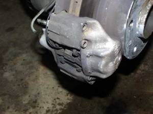
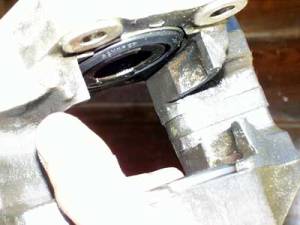
Before I began, the caliper looked like this:
Thanks to some guys on the forum and BCG group, I realized I didn't need to undo the hex bolts on the side, because that would split the caliper and it's a no-no for this type of caliper design. The solution is simplicity itself: Just drive out the two pins that span the caliper, and hold the anti-rattle spring and pads in place. Pads and spring then falls/pulls straight out.
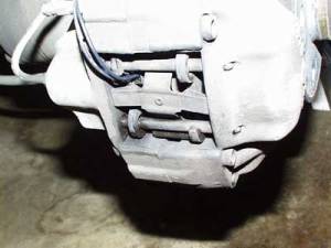 <----you can see how the pins hold the pads and spring together
drive out the two pins:
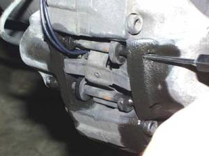
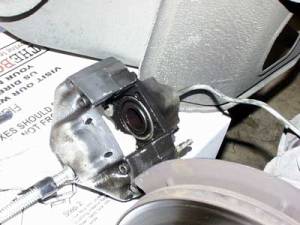
Here is what the caliper looks like after the spring is removed. One pad has a wear sensor which unplugs at a connector behind the rotor.
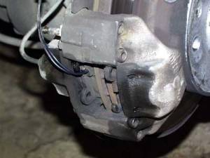 I supposed you can drive out the pins on the workbench, but I found this convenient, and I was just learning.
To remove the caliper, first remove and plug the brake line from the back.
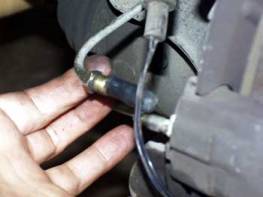
Then, remove the two big 17 mm bolts holding the entire caliper on.
Well, the problem was immediately apparent. Just look at this nasty messed up piston dust-seal!
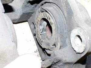
I had been told to drive out the pistons with compressed air. All I had was one of those pathetic cigarette lighter compressors. Anyway, that 30 psi was sufficient to drive out the better piston. The bad one however, took a lot of time and effort to get out. It was corroded and frozen.
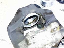
I cleaned the good piston with a kitchen scouring pad and installed it with the new o-ring and seal. Before I reinstalled the piston, I got everything clean with brake cleaner, compressed air, and a final bath in new brake fluid. The piston went back inside by finger pressure. There is a cut-out on each piston, which is supposed to be aligned at 20 deg (to horizontal?) so that it faces the incoming disk rotation, but I just guessed at this. Made sure the other side matched, though.
cleaning out the bore:
Here's a piston I cleaned and the new seals/o-ring.
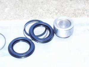
One down, one to go.
To drive out the bad piston, I finally resorted to C-Clamping the good one pushed in (with a protective rag) and hooked the caliper (sitting on a box) back to the brake line. I bled some brake fluid so it would re-fill the caliper. Then stomped on the brake and the stuck caliper came out 90 percent. I finally got the water-pump pliers from the tool kit on there and wiggled it out. There's a narrow neck at the end where you can grab it without damaging the smooth surface.
Reconnecting the caliper to free frozen piston hydraulically:
After getting both pistons cleaned out with new seals, installation was the reverse of removal. I bolted the caliper back on again, using Loctite, inserted the pads, spring, and hammered the pins back through.
Result: I'm really pleased to say it worked perfectly. The brake pads still had life left on them, so I reused them. The rotor looked very good and smooth. The most important thing, the brakes work great and are silent!
Contact Tom at tfholly@cox-internet.com with questions.